Maximum Measuring Accuracy
Linear ±0.000040″ (±0.001 mm)
Repeatability <0.000040″ (<0.001 mm)
Gage R & R ≤10% capability when measuring
high tolerance bores. Please contact Dyer with your application.
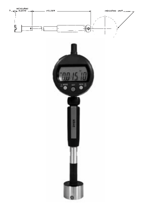
Used to measure the closest to the bottom of a bore
Contacts are set towards the bottom of the sleeve to allow the measurement to be as close to the bottom of the part as possible
Measuring at the top of the part requires a depth stop for added stability
Insertion chamfer is minimal to allow for max centering in the part
Carbide ball contacts are standard, but other materials are available upon request
240 Series Super Blind Part Numbers
| Sleeve Size Selection | Thru Bores | |
| Inch | mm | Tool Steel |
| 0.240–0.472 | 6.1–12 | 240-510 |
| 0.473–0.787 | 12.1–20.0 | 240-515 |
| 0.791–1.181 | 20.1–30.0 | 240-520 |
| 1.182–1.574 | 30.1–40.0 | 240-525 |
| 1.579–2.362 | 40.1–60.0 | 240-530 |
| 2.363–3.150 | 60.1–80.0 | 240-535 |
| 3.151–3.937 | 80.0–100.0 | 240-540 |
| 3.938–4.331 | 100.1–110.0 | 240-545 |
| 4.332–4.724 | 110.1–120.0 | 240-550 |
| 4.725–5.118 | 120.1–130.0 | 240-555 |
| 5.119–5.512 | 130.1–140.0 | 240-560 |
| 5.513–5.906 | 140.1–150.0 | 240-565 |
| 5.907–6.299 | 150.1–160.0 | 240-570 |
| 6.300–6.693 | 160.1–170.0 | 240-575 |
| 6.694–7.087 | 170.1–180.0 | 240-580 |
| 7.088–7.480 | 180.1–190.0 | 240-585 |
| 7.481–7.874 | 190.1–200.0 | 240-590 |
The “h” dimension is the distance from the centerline of the measuring contact to the bottom of the measuring sleeve.
• “h” = 1.0 mm for all Ø < 20mm
• “h” = is 1.2 mm for 20-60mm
• “h” = is 1.0 mm for all Ø > 60mm
• A complete setup includes a measuring sleeve, holder, indicator, and master ring