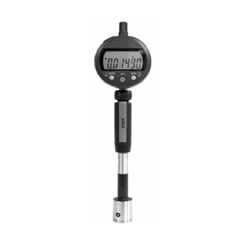
Maximum Measuring Accuracy
Linear ±0.000040″ (±0.001 mm)
Repeatability <0.000040″ (<0.001 mm)
Gage R & R ≤10% capability when measuring
high tolerance bores. Please contact Dyer with your application.
Used to measure bores without a bottom
Contacts are set towards the middle of sleeve to help stabilize gage in part before measurement
Insertion chamfer makes is easy for gage to enter part
Carbide ball contacts are standard, but other materials are available upon request
Special contact profiles are available: such as wedge, mushroom, and special radius versions
If the length of the bore is short, then a depth stop is recommended to stabilize gage in bore (See depth stop page for further details)
240 Series Thru Part Numbers
|
Sleeve Size Selection |
Thru Bores | |
| Inch | mm | Tool Steel |
| 0.098–0.117 | 2.5–3.5 | N/A |
| 0.118–0.157 | 3.0–4.0 | 240-400 |
| 0.158–0.236 | 4.1–6.0 | 240-405 |
| 0.240–0.472 | 6.1–12 | 240-410 |
| 0.473–0.787 | 12.1–20.0 | 240-415 |
| 0.791–1.181 | 20.1–30.0 | 240-420 |
| 1.182–1.574 | 30.1–40.0 | 240-425 |
| 1.579–2.362 | 40.1–60.0 | 240-430 |
| 2.363–3.150 | 60.1–80.0 | 240-435 |
| 3.151–3.937 | 80.0–100.0 | 240-440 |
| 3.938–4.331 | 100.1–110.0 | 240-445 |
| 4.332–4.724 | 110.1–120.0 | 240-450 |
| 4.725–5.118 | 120.1–130.0 | 240-455 |
| 5.119–5.512 | 130.1–140.0 | 240-460 |
| 5.513–5.906 | 140.1–150.0 | 240-465 |
| 5.907–6.299 | 150.1–160.0 | 240-470 |
| 6.300–6.693 | 160.1–170.0 | 240-475 |
| 6.694–7.087 | 170.1–180.0 | 240-480 |
| 7.088–7.480 | 180.1–190.0 | 240-485 |
| 7.481–7.874 | 190.1–200.0 | 240-490 |
| 7.875–9.000 | 200.1–230.0 | 240-616 |
The “h” dimension is the distance from the
centerline of the measuring contact to the
bottom of the measuring sleeve.
• “h” = 6 mm for Ø < 9mm
• “h” = 10 mm for Ø > 9mm
• Special “h” dim. are offered on request
• A complete setup includes a measuring
sleeve, holder, indicator, and master ring